🏠 Atari Jaguar Developer Reference ▸ CD-ROM Subsystem ▸ CD-ROM Hardware
CD-ROM Hardware
The Jaguar CD-ROM drive module: its place in the system, the Butch interface chip, the data path into Jerry, and the available schematics.
Source: Jaguar CD-ROM developer manual (scanned), © Atari Corp. 1995 (drive specs, Butch chip, data path); sources/Schematics/Jaguar CD ROM.pdf and sources/Other Documents/Jag CD testpro4.pdf (schematic / test spec). The 1995 manual documents the drive only as far as is needed for software development — direct hardware access is not supported (use the CD BIOS).
The drive module
The Jaguar CD is an external add-on that sits on the cartridge/expansion port and provides a double-speed CD mechanism. Key specs (see Overview for the full table):
| Property | Value |
|---|---|
| Capacity | 746.9 MB |
| Speed | Double speed, ≈353 kb/sec |
| Sustained rate | 352,800 bytes/sec |
| Block size | 2352 bytes (588 longs) |
| Uncorrectable error rate | < 1 in 10¹¹ (all errors flagged) |
The 1994 Jaguar CD-ROM Drive Module Test Specification (sources/Other Documents/Jag CD testpro4.pdf) is a manufacturing document (in-circuit test, static burn-in, PCBA functional test, diagnostics) rather than a programming reference — useful only for hardware/repair work.
Butch — the CD interface chip
CD data enters the Jaguar through the Butch interface chip, which redirects
the CD data stream onto Jerry’s I²S serial interrupt. This is why the
CD BIOS loads GPU (or DSP) interrupt code to
service those interrupts, and why you must not enable unrelated JINTCTRL
interrupts while a read handler is active.
Two revisions exist and they affect which BIOS you can run:
| Chip | BIOS support | Identifying it |
|---|---|---|
| Butch 1 | CD BIOS rev 2 only | older development CD systems |
| Butch 2 | rev 2 or rev 4 | CD system in a modified production-level case |
See Calling convention for how the BIOS revision is selected.
Data path
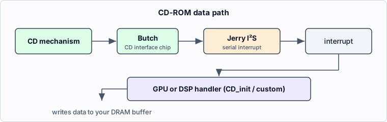
- GPU path (the
CD_initfamily): the BIOS installs a GPU ISR that runs off the redirected Jerry I²S interrupt. Tight latency budget (~54 µs usable at double speed) — see the latency rule. - DSP path (optional): your own DSP I²S handler with
CD_jeriandSMODE = $14; subject to rare unreported data errors, so checksum critical data. - Audio path:
CD_jerican route CD data straight to Jerry’s I²S so audio enters without consuming main system bandwidth (see Audio Subsystem).
Relevant registers (SMODE, the I²S serial registers, JINTCTRL) are documented
in the Memory Map / Register List and
Serial I/O.
Schematics
- sources/Schematics/Jaguar CD ROM.pdf — the CD-ROM unit schematic
(
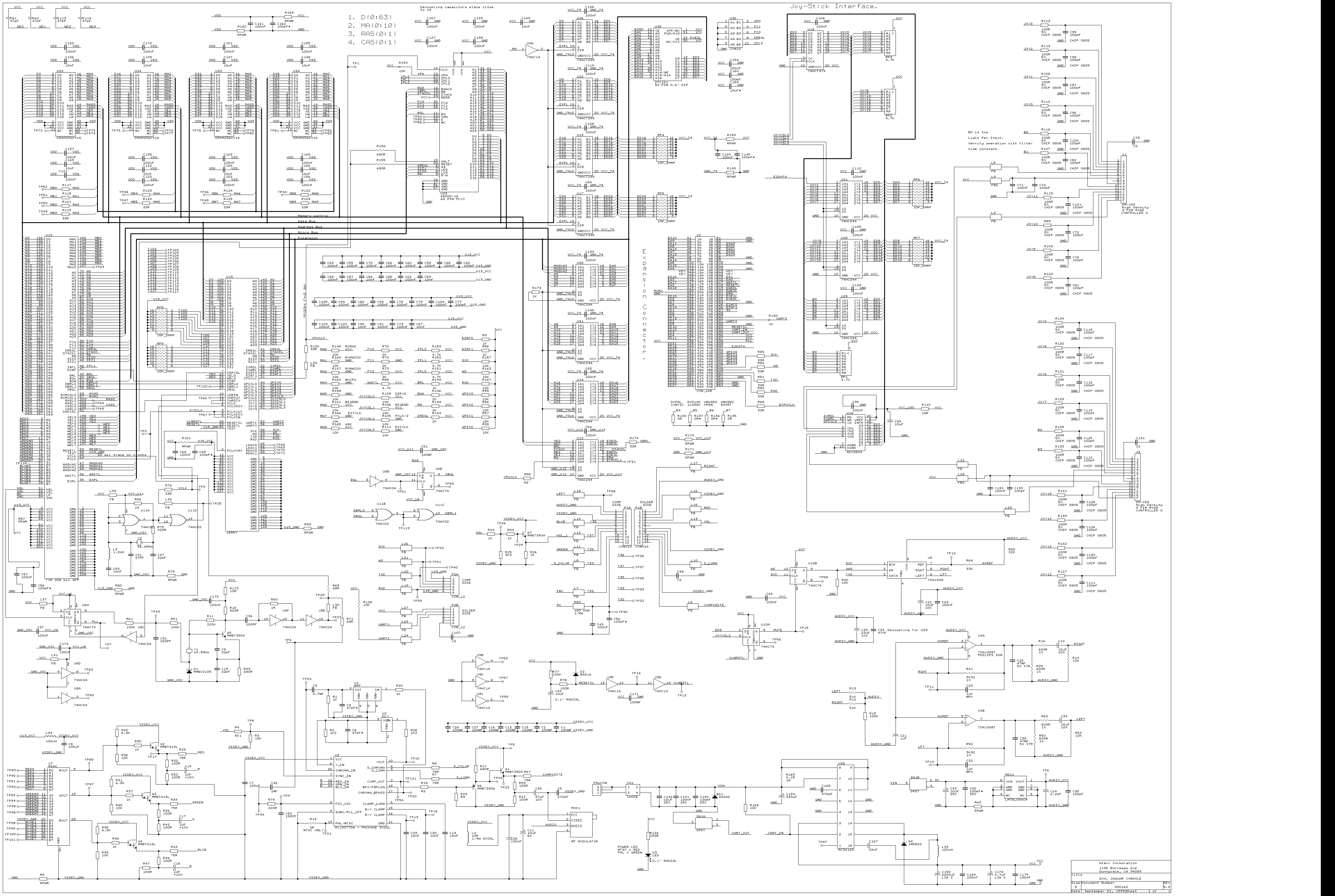
JAGCDROM.SCH, Atari Corporation). It is a multi-sheet schematic referencing sub-sheetsDROPOUT.SCH,SERVO.SCH, etc., covering the RF/servo/laser front end and the digital interface. The PDF carries the net/title-block data but is a drawing, not prose — open it directly for pin-level detail. - The main Jaguar console schematic (sources/Schematics/Jaguar Schemaic (Clear).pdf / console schematic PNG) shows the cartridge/expansion port the CD module attaches to; see Video & System Clocks, Timing → ports.
See also
- CD-ROM Subsystem Overview
- CD-ROM BIOS API
- Serial I/O — ComLynx, MIDI, Synchronous Serial
- Audio Subsystem & Synthesis
- Memory Map / Register List
◀ Prev: CD-ROM Programming Procedures & Guidelines · 🏠 Home · Next: Sample Programs ▶
Jump to: Architecture · Memory Map · Registers · Instructions · Glossary · CD-ROM