🏠 Atari Jaguar Developer Reference ▸ Architecture & Memory ▸ System Architecture Overview
System Architecture Overview
The Atari Jaguar is a custom chip set intended as the heart of a high-performance games machine. Beyond a general-purpose CPU, it provides five processing elements spread across two custom ASICs.
Source: Software Reference Manual — Tom & Jerry (V10), pp. 6–10; Technical Overview (V10), pp. 3, 9; Appendix (Atari original, 26 April 1995), Appendices A & B. Originally © Atari Corp. 1995.
The two custom chips
| Chip | Code name | Contains |
|---|---|---|
| Tom | graphics ASIC | Object Processor, Graphics Processor (GPU), Blitter, memory controller, video timing |
| Jerry | sound/I-O ASIC | Digital Sound Processor (DSP), timers, serial interfaces, joystick interface |
Alongside them sits an external CPU — a Motorola 68000 — which acts as the system manager.
The five processors
-
CPU (68000) — the manager. Handles communication with the outside world and coordinates the other processors. It sits at the highest level of control flow and has complete control of the system. It is not the performance path; heavy lifting belongs to the coprocessors.
-
Object Processor (in Tom) — generates the display. For each scan line it executes a list of commands (the object list) and assembles that line into an internal line buffer. Objects can be scaled/unscaled bit-maps, can perform conditional branches within the list, and can interrupt the GPU. It is both a sprite engine and a framebuffer system. See Object Processor.
-
Graphics Processor (GPU) (in Tom) — a very fast RISC microprocessor optimized for graphics generation, with 4 KB of fast internal RAM, a parallel multiplier, a barrel shifter, and a divide unit. Executes in parallel with the other units. See Graphics Processor.
-
Blitter (in Tom) — tightly coupled to the GPU; moves and fills graphical data 64 bits at a time, with hardware Gouraud shading, Z-buffering, line drawing, character painting, and image rotation. See Blitter.
-
Digital Sound Processor (DSP) (in Jerry) — architecturally similar to the GPU but aimed at sound synthesis and sampled-sound playback, with 8 KB of fast internal RAM. Can also be used for general processing. See DSP.
How they cooperate
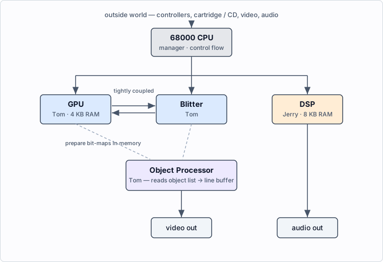
- The CPU manages the system and feeds the coprocessors.
- The GPU + Blitter typically work together to render bit-maps into memory.
- The Object Processor reads the object list and composites those bit-maps into the displayed scan lines.
- The DSP runs independently for audio, tightly coupled to Jerry’s timers and interrupts.
Memory and the data path
The Jaguar gives these blocks a 64-bit data path to external memory and can
sustain a very high transfer rate into DRAM. Main system RAM is 64 bits wide: a
single 2 MB bank starting at $00000000. Hardware registers and the GPU/DSP
internal SRAM live higher in the map (GPU/DSP RAM from $00F00000).
The GPU, DSP, and Blitter internal registers are 32 bits wide and must be read and written as 32-bit entities by the 68000. Transfers to GPU/DSP internal SRAM must be long-word aligned. To clear a long in internal RISC RAM, use
move, notclr.l(which is unreliable there — a documented hardware bug).
Full details: Memory Map / Register List.
Bus bandwidth and performance
All five processors share the single 64-bit bus, so memory bandwidth — not raw clock speed — is usually the limiting factor. Atari’s own programming guidelines reduce to a few rules:
- ROM is slow — up to ~10× slower than DRAM. Do not run 68000 code, build or read an object list, or display bitmap data directly from ROM. Copy code and data into RAM first; an object list run from ROM may slow dramatically or fail outright.
- Keep the 68000 off the bus. It is the system manager, not the performance
path. When idle, halt it with
STOPso the Object Processor, Blitter, GPU, and DSP get the bus. For time-critical 68000 routines (e.g. a vertical-blank handler), copy them to RAM and execute there so instruction fetches don’t hog the bus. See GPU → Performance notes. - Move memory with the Blitter, not the 68000/GPU/DSP, and use the Blitter in phrase mode wherever possible — it is much faster. You can start a blit and keep computing on the GPU or DSP until it completes.
- Run the GPU and DSP concurrently; offload as much as possible from the 68000 onto them.
- Minimize interrupt-handler time — optimize all interrupt code to the absolute minimum, since it steals bus cycles from everything else.
Source: Appendix (Atari original, 26 April 1995), Appendix A and Appendix B (“Programming Tips & General Procedures”).
Two color resolutions
Tom supports 24-bit (true color) and 16-bit modes. The 16-bit modes include CRY (Cyan-Red-Intensity), which is cheap to Gouraud-shade and nearly indistinguishable from 24-bit. See CRY Color & Color Mapping.
See also
◀ Prev: Home · 🏠 Home · Next: Memory Map / Register List ▶
Jump to: Memory Map · Registers · Instructions · Glossary · CD-ROM