🏠 Atari Jaguar Developer Reference ▸ Architecture & Memory ▸ Connectors, Pinouts & Power
Connectors, Pinouts & Power
A hardware-reference hub for the Atari Jaguar’s power supply, connector pinouts, and schematic drawings — covering the power-brick specification, console and CD-unit current consumption, and an index of the available schematics, with links to the full pinout tables documented elsewhere.
Source: Technical Reference Manual (V10) appendixes; the Jaguar schematics. © Atari Corp. 1995.
Power supply
From new, both the Jaguar console and the CD unit are supplied with a power supply unit (PSU) that plugs straight into the wall outlet. The standard “brick” provides an unregulated 9 V DC at 1.2 A (1200 mA) through a 2.1 mm DC barrel connector. The polarity is unusual: the outer barrel is positive (+, 9 V) and the inner/center tip is negative (−, 0 V).
| Specification | Value |
|---|---|
| Output voltage | 9 V DC (unregulated) |
| Output current | 1.2 A (1200 mA) |
| Connector | 2.1 mm DC barrel |
| Polarity | Outer = positive (+, 9 V); inner/center tip = negative (−, 0 V) |
Replacement guidance
If the original PSU needs replacing and an original Jaguar replacement cannot be found, two types of third-party replacement are available — regulated (a.k.a. stabilized) and unregulated:
- Unregulated replacements must match the voltage, current, and polarity specifications above exactly, or the Jaguar may be damaged.
- Regulated replacements must match the voltage and connection type/polarity, and may supply more (but not less) than 1.2 A of current.
If there is no clear indication that a chosen replacement is regulated, assume it is unregulated. This can be checked by measuring the output voltage with a multimeter/DVM while disconnected from the Jaguar: a regulated unit reads 9 V, whereas an unregulated unit reads higher — typically 12 V – 14 V.
Current consumption
| Device | Current draw |
|---|---|
| Standard Jaguar (game + 2 joypads) | 560 mA average (can reach 800 mA) |
| Standard Jaguar CD unit | 650 mA peak |
Single-brick limitation
The Technical Reference Manual recommends limits for the current that may be drawn from the Jaguar’s controller, expansion (cartridge), video, and DSP ports, and these should not be exceeded. Because the standard Jaguar power brick is only capable of supplying 1.2 A (1200 mA), it is not possible to power both the Jaguar console and the CD unit from a single standard power brick — the combined draw exceeds the brick’s rating. The CD unit therefore uses its own supply.
Connector & port pinouts
The Jaguar’s external hardware ports are documented in full elsewhere; this page links rather than duplicating those tables. A one-line summary of each follows.
- Cartridge / Expansion Port — a custom 50-pin (54-position) double-row PCB edge connector carrying the expansion address (
EA*) and data (ED*) buses, serial signals (SCK/WS/TXD/RXD), GPIO,CART_IN/CART_OUT, VCC, and an unregulated 9 V rail (row B, pin 27). Full pinout in Video & System Clocks, Timing. - DSP Port — a custom 12-pin two-row edge connector with the synchronous serial interface (SCK, WS, TXD, RXD), asynchronous UART TXD/RXD, ground, and a +5 V, 50 mA-maximum rail (pin 1B). All active signals are 5 V TTL. Full pinout in Video & System Clocks, Timing.
- Video Connector — a custom 24-pin two-row edge connector providing composite, S-Video (Luma/Chroma), and RGB video, EIAJ line-level stereo audio, sync, and a 9 V DC, 100 mA-maximum rail (pin 11A). Full pinout in Video & System Clocks, Timing.
Controller connectors
Each of the two controller ports (Port 1 = left, Port 2 = right) is a DB15 connector providing four bi-directional digital pins, six input-only digital pins (4 + 2 button), a +5 V, 50 mA-maximum rail (pin 7), ground, and (on Port 1) a light-pen/light-gun input shared with B0 (pin 6). The full signal/pin-out table and the controller scan matrix are documented in Controllers & Controller Ports.
The standard joypad’s internal circuitry (per its schematic) uses two 74HC244 octal buffers to drive the matrix, 4K7 pull-up resistors throughout, and 1N4148 diodes for the controller matrix. The controller-ID diode (D21) is not fitted on a standard joypad — C2 and C3 read high to indicate a standard controller — and is shown in the schematic for reference only, to illustrate how a bank-switching controller pulls C2 low to identify itself.
Schematic diagrams
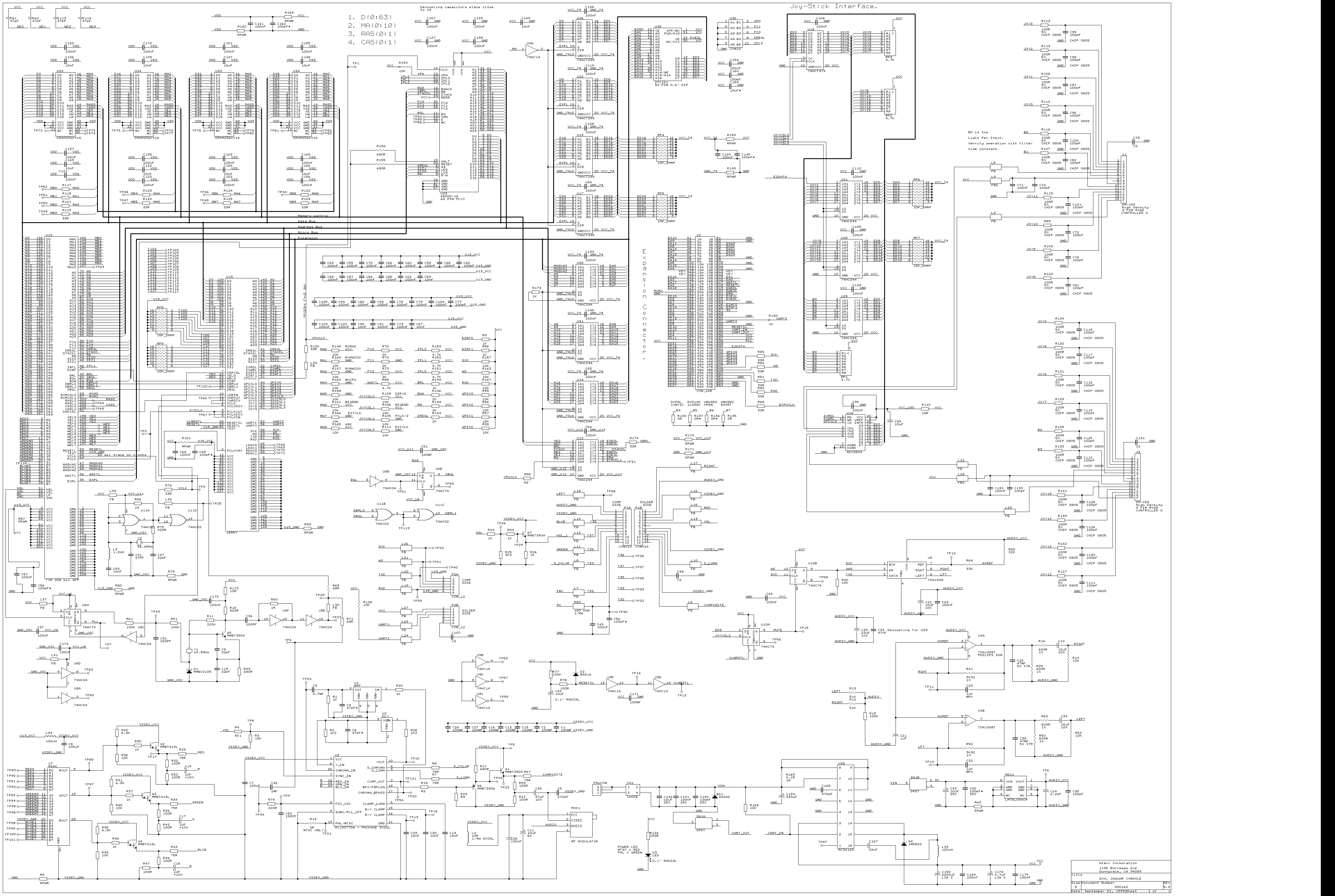
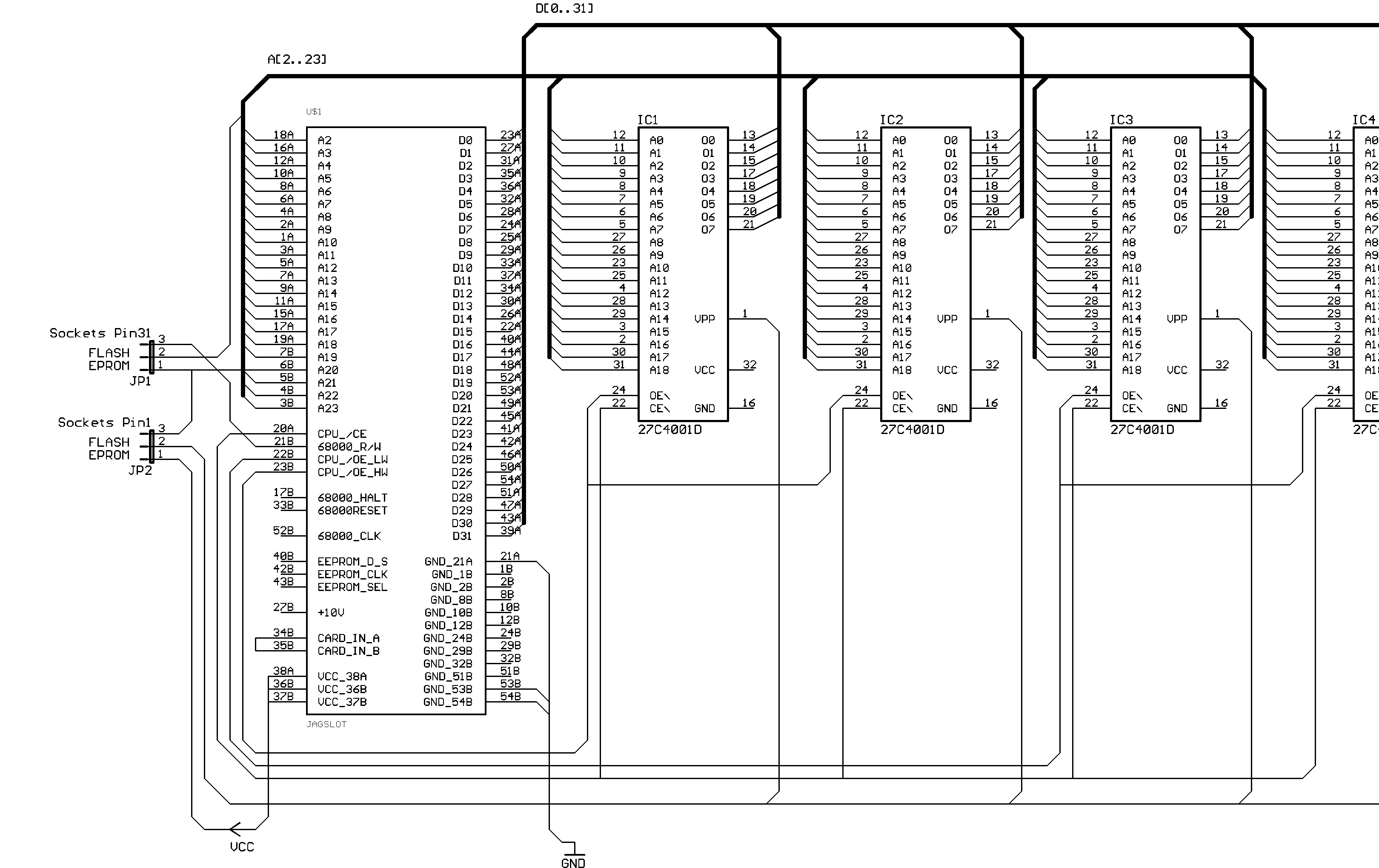
The following drawings are available under sources/Schematics/. Wire colors indicated on the controller schematics may not be the same in all controllers.
| Drawing | Source file(s) | Notes |
|---|---|---|
| Jaguar console | sources/Schematics/Jaguar Schemaic (Clear).pdf, sources/Schematics/Jaguar schematics (Clear).png | Clear version of the console schematic (PDF and PNG). |
| CD unit | sources/Schematics/Jaguar CD ROM.pdf | Jaguar CD-ROM peripheral schematic. |
| Standard controller | sources/Schematics/Jaguar Standard Controller.pdf | Controller-ID diode D21 shown for reference only (standard joypad reads C2/C3 high). |
| Pro controller | sources/Schematics/Jaguar Pro Controller.pdf | Additional buttons are simply wired in parallel with their standard equivalents. |
| Rotary “Tempest” controller | sources/Schematics/Jaguar Rotary Controller.pdf | Diode D21 (C3 in the matrix) shown for reference, indicating how the rotary controller is identified. |
| Team Tap (4-player adaptor) | sources/Schematics/Jaguar Team Tap.pdf | Diode D25 identifies the Team Tap by pulling J1 of socket 3 (C1 in the matrix) low; C1 is high for all other sockets/controllers. |
| Cartridge pinout | sources/Schematics/jagcart.gif | Cartridge connector pinout image. |
Cartridge parts
Provided for information only; other sources may be available.
- PCBs — new, unpopulated 4 Mb and 6 Mb Jaguar cartridge PCBs can be purchased from Clint Thompson (contact via private message on AtariAge or e-mail
info@riscgames.com). - Decoupling capacitors — in addition to the EPROMs, you will need 0.1 µF (100 nF), 16 V multilayer ceramic / ceramic-plate decoupling capacitors with 0.2” (200 thou / 5 mm) pitch, purchased separately.
- Shells (cases) — new cases in several colors are available from AtariAge member “Starwander”’s website.
For EPROM/EEPROM part numbers and the chip-byte ordering used when building cartridges, see Cartridges, EEPROM Saves & ROM Building.
See also
- Video & System Clocks, Timing — full port pinouts
- Controllers & Controller Ports — controller pinouts & matrix
- Cartridges, EEPROM Saves & ROM Building
- Memory Map / Register List
- CD-ROM Hardware
◀ Prev: Cartridges, EEPROM Saves & ROM Building · 🏠 Home · Next: Motorola 68000 — Programmer’s Model ▶
Jump to: Architecture · Memory Map · Registers · Instructions · Glossary · CD-ROM